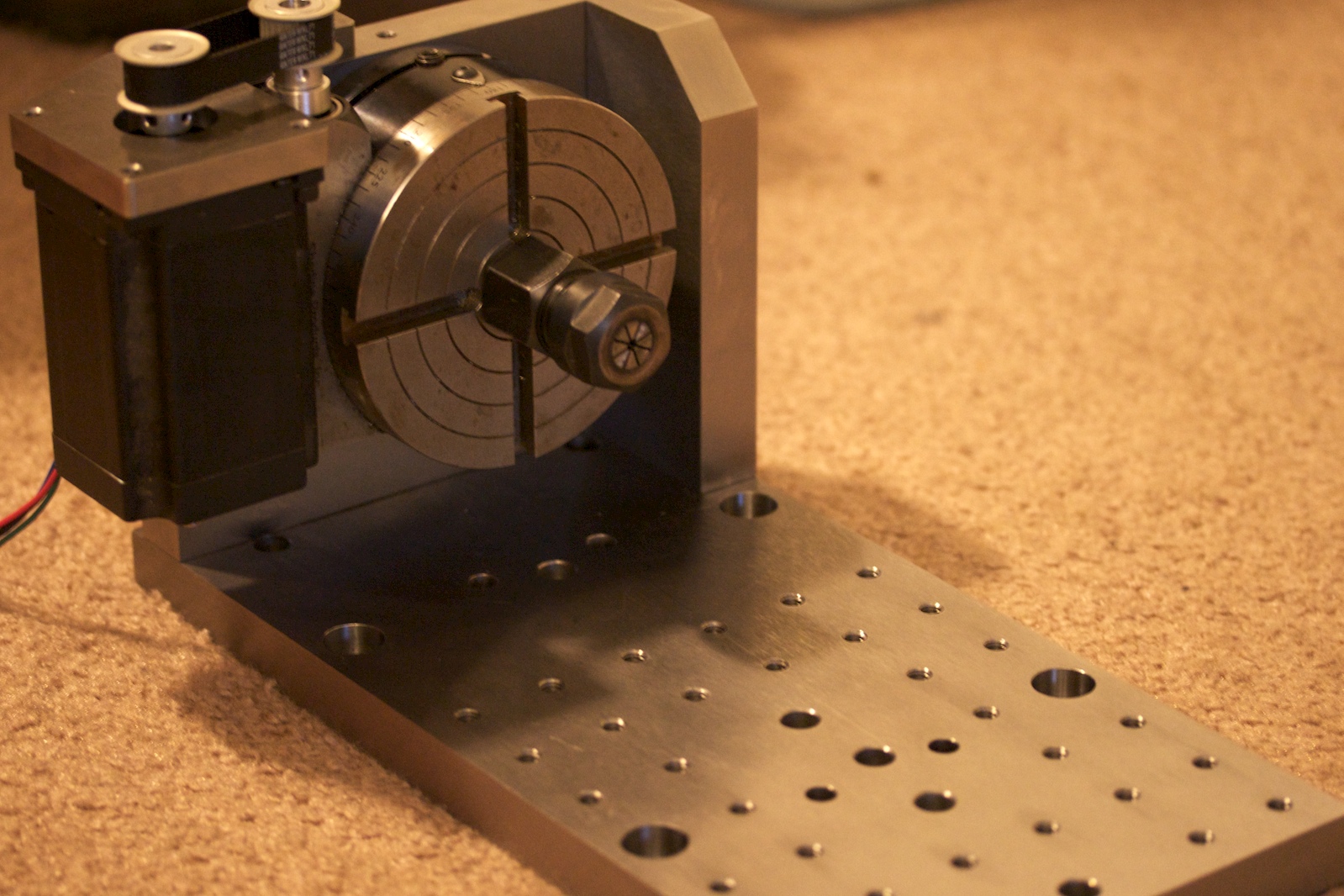

Finishing up some work on the 4th axis setup for the milling machine. This was also designed in Alibre (along with entirely remodeling the entire milling machine, a story for another post). This will allow controlled rotation of a workpiece parallel to the X axis of travel. One can reach more sides of a part with a greater variety of cutters. It can also reduce the amount of different setups required to make a single part, saving time and difficulty. I purchased the rotary table some time ago for use with a manual milling machine. The standard mounting for a stepper motor will not fit this design, so I constructed my own using a bracket and some timing belts. Here the rotary table is shown with a collet setup, which allows holding work up to 3/8" in diameter. A larger capacity chuck is on it's way to hold larger work, as well as non round parts.
A matrix of holes was drilled in the table opposite the rotary table to allow the use of optional accessories such as a tailstock for work support, or to simply use to mount additional vises or fixturing. One more part still needs to be fabricated, a sheet metal cover to protect the belt and pulleys from chips and debris. Although this part does not require high precision to work well, I am curious to see how Alibre's sheet metal design translates into real parts.

This plate aligns the table shown above with the base of the mill table. It allows me to either mount this table setup, or an alternate one with a vise. The dowel pin holes control the alignment so that each one is mounted in the same location it was last. Flanking each dowel pin hole are two tapped holes. These holes hold longer set screws which are used to raise this plate off the dowel pins. This entire setup weighs close to 40 pounds so the screws enable easy removal without damage or injury.
The same interface will also be used when making a table for working with larger sections of flat stock.
No comments:
Post a Comment